View all work返回全部项目
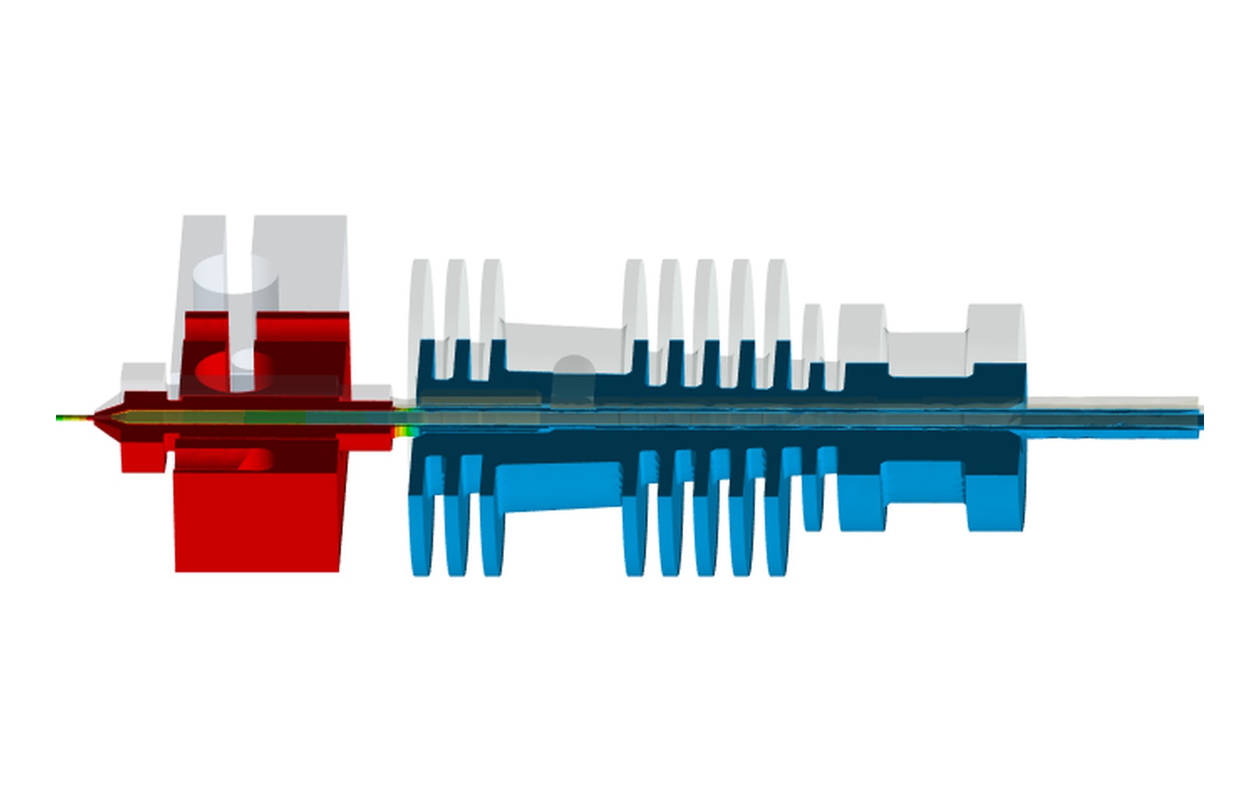
Steady-state thermal FEA of the final hotend design — heater block at 230 °C, heat-sink held near ambient
Project · ENG5105

3D-Printer Hotend Retrofit3D 打印机热端改装

An ENG5105 client project for ForgeFab: redesign a 3D-printer hotend so a batch of mistakenly-bought Prusa MK4 nozzles can run on the older MK3 S+ platform — benchmarked with thermal & structural FEA, consolidated into a manufacturable, serviceable design.ENG5105 客户项目(ForgeFab):重设计 3D 打印机热端,让误购的一批 Prusa MK4 喷嘴能用在较旧的 MK3 S+ 平台上——用热与结构 FEA 做基准,整合成可制造、易维护的设计。

Role角色Team / pod (ENG5105)小组 / pod(ENG5105)
Type类型Thermal + structural FEA热 + 结构 FEA
Tools工具ANSYS · SolidWorksANSYS · SolidWorks
Client客户ForgeFab TechnologiesForgeFab Technologies
Year年份20242024

The brief was unusually concrete: ForgeFab had bought a batch of Prusa i3 MK4 nozzles that don't fit their MK3 S+ printers. Throwing them out would be waste — so the task was to retrofit, not replace.任务异常具体:ForgeFab 误购了一批 Prusa i3 MK4 喷嘴,装不进他们的 MK3 S+ 打印机。扔掉是浪费——所以任务是改装适配,而非替换。

01The client brief客户需求

Adapt the MK4 nozzle to run on the MK3 S+ without compromising print quality, dimensional accuracy or speed — a sustainability-driven retrofit (UN SDG 12, responsible consumption). That meant resolving the geometric, thermal and interface mismatches between two printer generations, around a specified heating element, heat-break and extruder.让 MK4 喷嘴在 MK3 S+ 上运行而不牺牲打印质量、尺寸精度与速度——一个可持续驱动的改装(联合国 SDG 12,负责任消费)。这意味着围绕指定的加热元件、热断与挤出机,解决两代打印机之间的几何、热与接口不匹配。
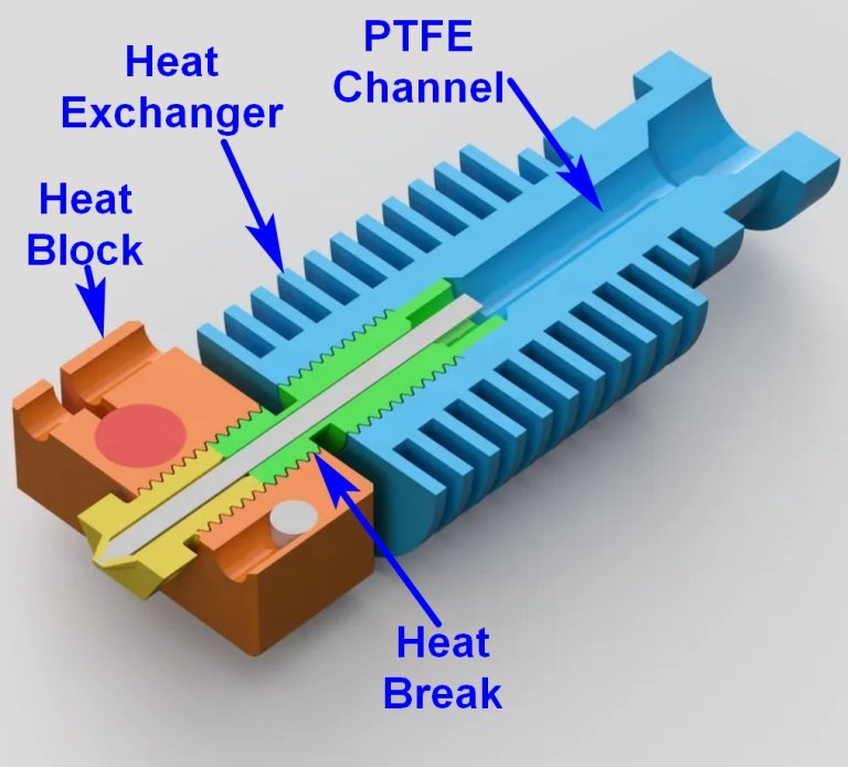
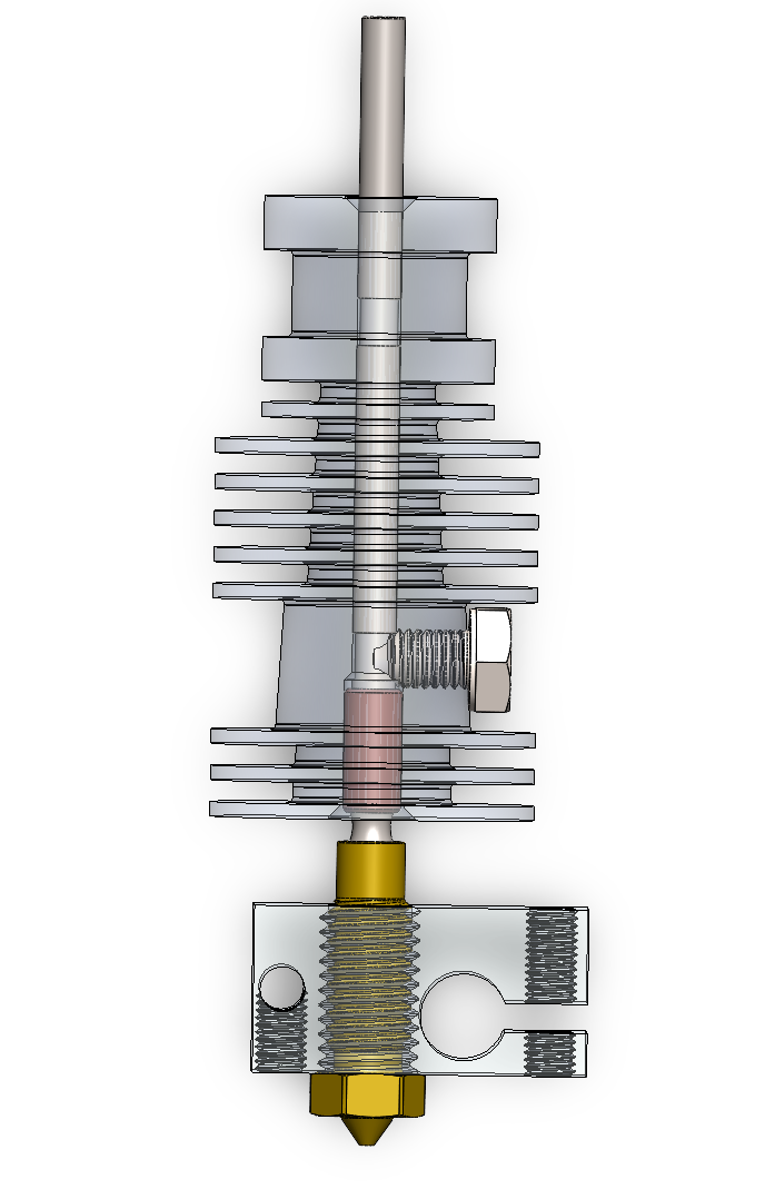
Cutaway of the hotend thermal path — heat block, heat break, PTFE channel and finned heat exchanger.
The thermal path in cutaway — heat block, heat break, PTFE channel and the finned heat exchanger. Everything above the heat break must stay cool; everything below must stay hot.剖视下的热路径——加热块、热断、PTFE 通道与鳍片式换热器。热断以上必须保持冷,以下必须保持热。

02Benchmarking the baseline基准测试

First we established what 'good' looks like by benchmarking the MK3 S+ hotend — both physically (print tests, thermal-imaging) and numerically (static and steady-state thermal FEA in ANSYS) — so any retrofit could be held to or above that baseline.我们先通过对 MK3 S+ 热端做基准测试来确立「好」的标准——既有物理测试(打印试验、热成像),也有数值分析(ANSYS 静力与稳态热 FEA)——使任何改装都能对齐或超越该基线。
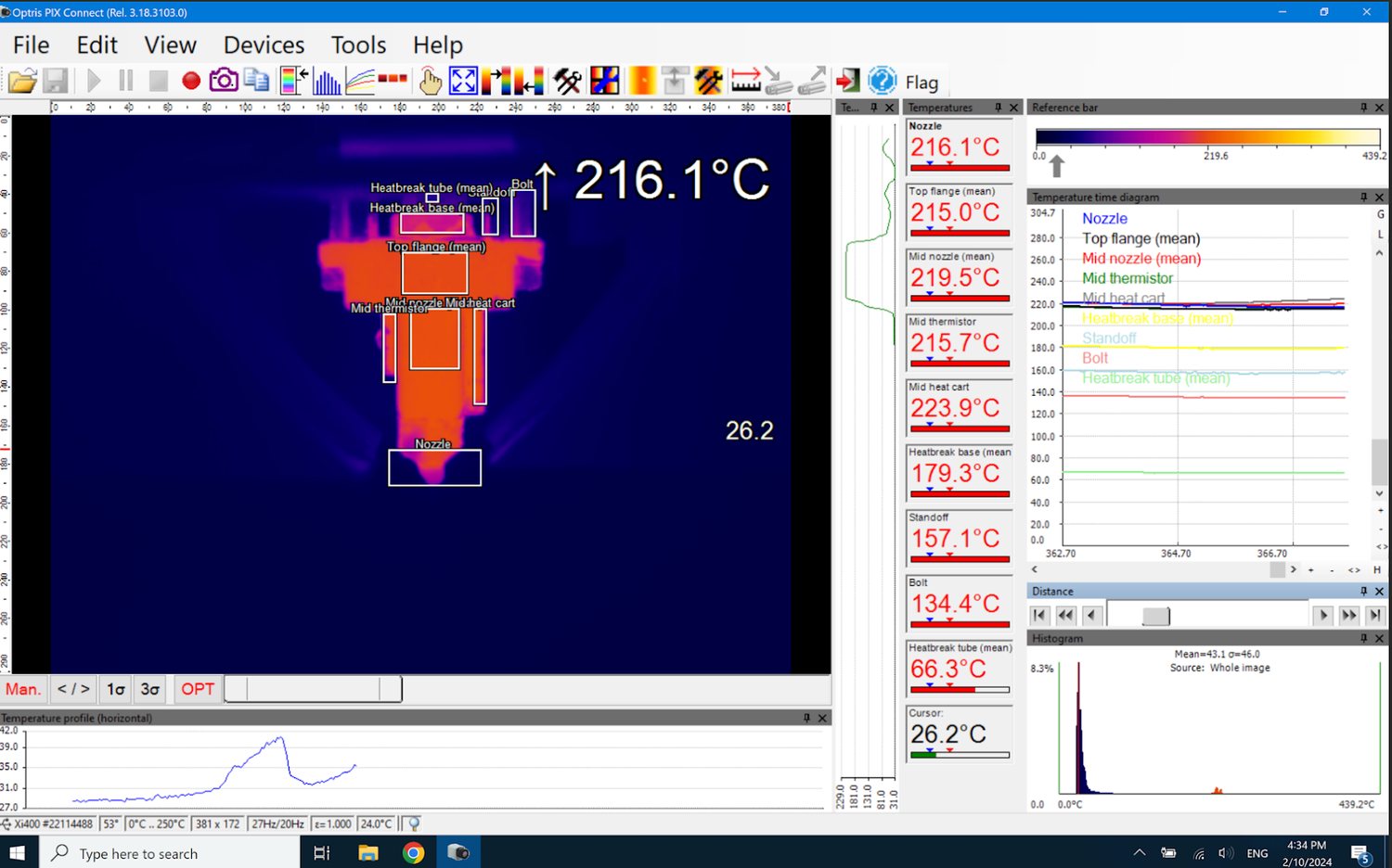
Infrared thermography of the running hotend — nozzle region at ~216 °C.
IR thermography of the running baseline — the nozzle region reads ~216 °C, anchoring the FEA boundary conditions in measurement.基线运行时的红外热成像——喷嘴区约 216 °C,为 FEA 边界条件提供实测锚点。
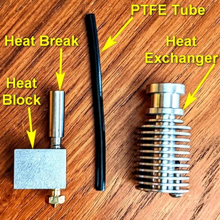
The physical hardware — heat block, heat break, PTFE tube and heat exchanger.
The physical parts on the bench — heat block, heat break, PTFE tube and heat exchanger.台面上的实物——加热块、热断、PTFE 管与换热器。

The steady-state thermal model puts the heater cartridge at 211 °C with the heat-sink held near ambient — within about 2% of the 216 °C read by the IR camera. The static-structural case, by contrast, peaks at just 0.37 MPa at the heat-break neck under gravity and print-head acceleration: the hotend is a thermal design problem, not a structural one, and the FEA effort was weighted accordingly.稳态热模型给出加热棒 211 °C、散热器接近室温——与红外相机读到的 216 °C 相差约 2%。相比之下,静力学工况在重力与打印头加速度下最大应力仅 0.37 MPa,出现在热断颈部:热端是一个热设计问题而非结构问题,FEA 的精力也据此分配。
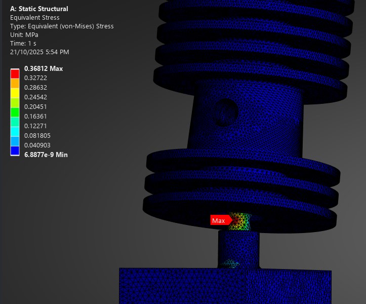
Equivalent (von-Mises) stress of the final hotend design — 0.37 MPa maximum at the heat-break neck.
Equivalent (von-Mises) stress on the final design — 0.37 MPa maximum at the heat-break neck, the rest of the assembly essentially unloaded.最终设计的等效(von-Mises)应力——最大 0.37 MPa,位于热断颈部,其余部位基本无载荷。

03Consolidating to the final design整合出最终设计

Several pod concepts were proposed; through a weighted evaluation (thermal performance, manufacturability, ease of maintenance, MK4 compatibility, reliability) they were consolidated into one integrated design — keeping the proven nozzle-fastening method while improving the heat path and serviceability.pod 内提出多个概念;经加权评估(热性能、可制造性、易维护、MK4 兼容、可靠性)整合成一个集成设计——保留经验证的喷嘴紧固方式,同时改善热路径与可维护性。
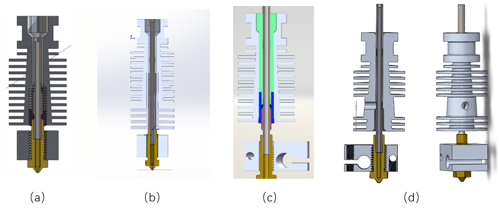
The four pod concepts (a)–(d) compared before consolidation.
The four pod concepts, (a)–(d), placed side by side before the weighted evaluation consolidated them into one design.加权评估前并排比较的四个 pod 概念 (a)–(d),之后整合为一个设计。
  • Materials & interfaces: Al-6061 heat-sink, C145 copper heater block and brass nozzle, with realistic contact-conductance values at the assembly joints.材料与接口:Al-6061 散热器、C145 铜加热块、黄铜喷嘴,装配结合处设真实接触热导。
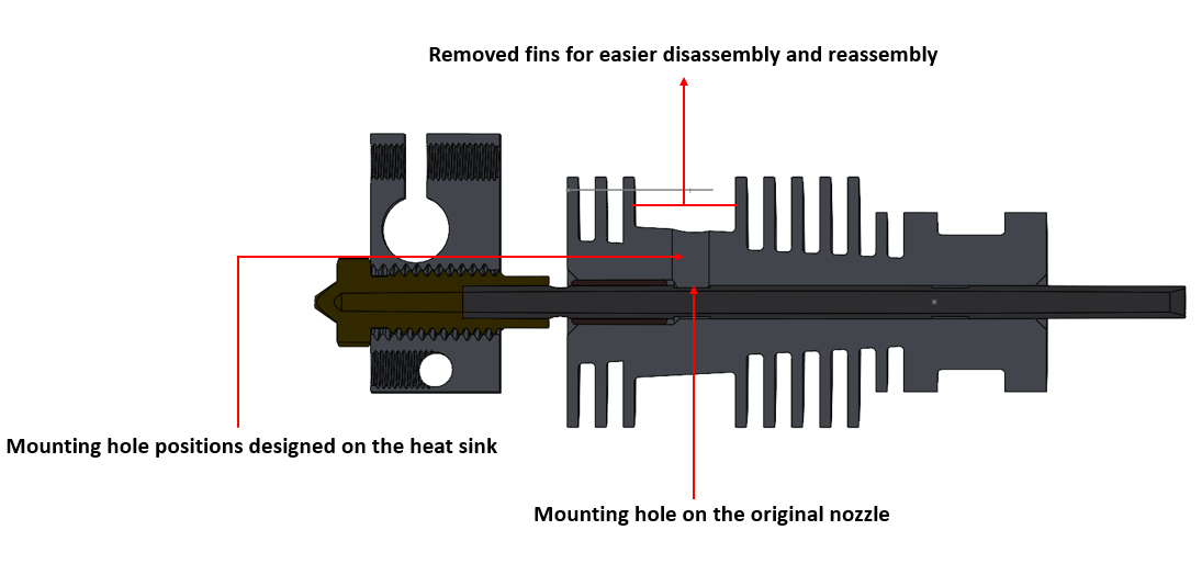
  • Serviceability: mounting holes re-aligned to the existing screw pattern and adjacent fins removed for tool access, so a nozzle swap is fast (M4×0.7 fastener, anti-rotation key slot).可维护性:安装孔对齐原有螺纹,移除相邻鳍片留出工具通道,使换嘴更快(M4×0.7 紧固 + 防转键槽)。
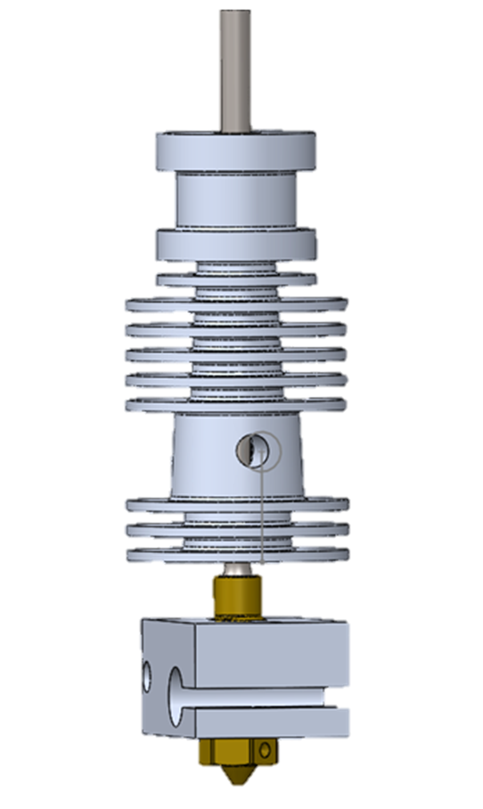
The consolidated hotend assembly — heat-sink fins, C145 copper heater block and brass nozzle — modelled in SolidWorks for the MK3 S+ retrofit.
The consolidated hotend assembly — heat-sink fins, C145 copper heater block and brass nozzle — modelled in SolidWorks for the MK3 S+ retrofit.整合后的热端总成——散热鳍片、C145 铜加热块与黄铜喷嘴——在 SolidWorks 中为 MK3 S+ 改装建模。
Section through the final hotend assembly — PTFE liner, heat break, set-screw, brass nozzle in the heater block.
The same assembly in section — the PTFE liner (pink) sits inside the heat break, an M4 set-screw clamps the heat break into the heat-sink, and the brass nozzle threads into the heater block.同一总成的剖视——PTFE 衬管(粉色)位于热断内,一颗 M4 紧定螺钉把热断锁在散热器上,黄铜喷嘴旋入加热块。
Serviceability features called out on the design — mounting holes aligned to the original screw pattern, fins removed for tool access.
Serviceability, annotated — mounting holes re-aligned to the original screw pattern, and fins removed where a tool needs to reach for disassembly.可维护性标注——安装孔对齐原有螺纹位置,并在工具需要伸入拆装处移除鳍片。
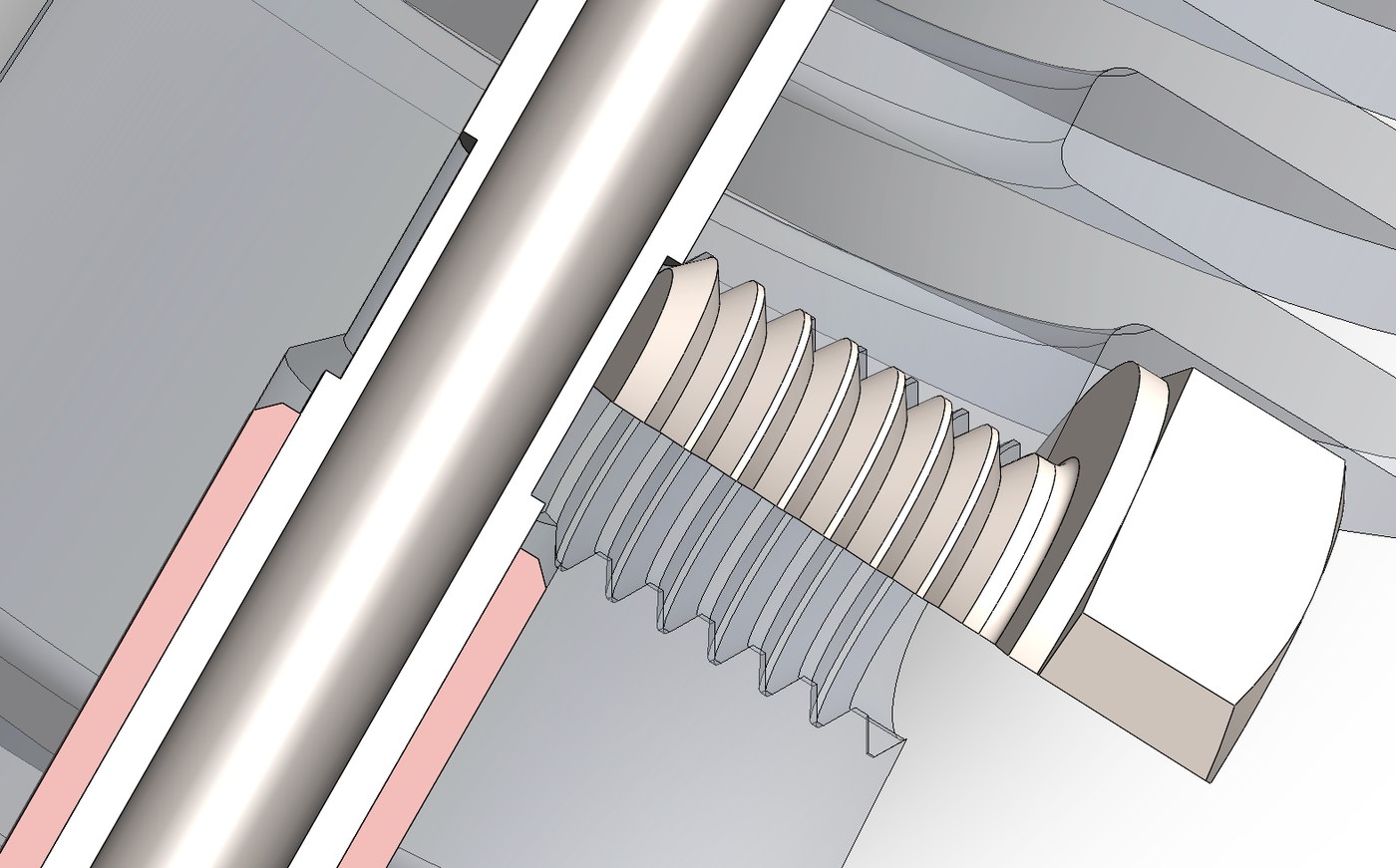
Close-up of the set-screw thread engagement clamping the heat break.
Close-up of the set-screw engagement — the M4×0.7 thread bears on the heat-break flat to fix it axially without crushing the PTFE liner.紧定螺钉啮合特写——M4×0.7 螺纹顶在热断的平面上实现轴向固定,而不压溃 PTFE 衬管。

04Simulation & verdict仿真与结论

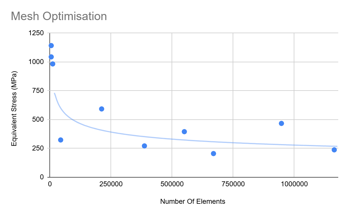
A steady-state thermal FEA (quadratic mesh, ~0.96 M elements) was mapped into a structural model to check stiffness and safety, and inner-wall heat-flux was integrated to quantify the energy pathways. A mesh-independence sweep justified the element count before any result was trusted.稳态热 FEA(二次网格,~0.96 M 单元)映射到结构模型核对刚度与安全,并对内壁热流积分量化能量通路。任何结果被采信前,先用网格无关性扫掠确定单元数。
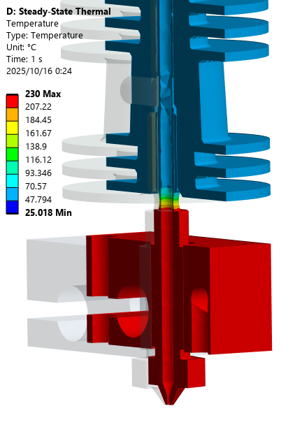
Steady-state thermal field of the final design — cool blue heat-sink, hot red heater block at 230 °C.
The final design's steady-state thermal field — heater block at 230 °C, heat-sink held cool, the gradient concentrated in the heat break as intended.最终设计的稳态热场——加热块 230 °C,散热器保持低温,温度梯度如设计意图集中在热断处。
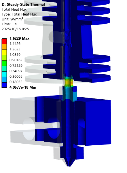
Total heat flux through the final design — peak 1.6 W/mm² in the heat-break neck.
Total heat flux — the leak path up the heat-break neck peaks at 1.6 W/mm²; integrated over the neck's wall that is only a few watts of the 40 W heater, the rest leaving through the block and nozzle.总热流——沿热断颈部向上的泄漏路径峰值 1.6 W/mm²;对颈部壁面积分后只有几瓦,40 W 加热功率的其余部分经加热块与喷嘴散出。
Mesh-independence study — equivalent stress vs element count up to ~1.2 M elements.
Mesh-independence study — the solution settles as the element count approaches ~1 M.网格无关性研究——单元数接近 ~1 M 时解趋于稳定。
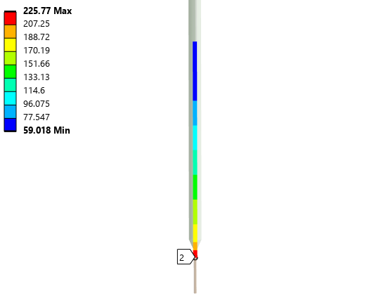
Temperature along the filament path — 226 °C at the nozzle down to 59 °C at the top of the heat-sink.
Temperature along the filament path — 226 °C at the nozzle falling to 59 °C at the top of the heat-sink, so the melt zone stays confined below the heat break.沿耗材路径的温度——喷嘴处 226 °C,到散热器顶部降至 59 °C,熔融区被限制在热断以下。

05Ready for manufacture为制造做好准备

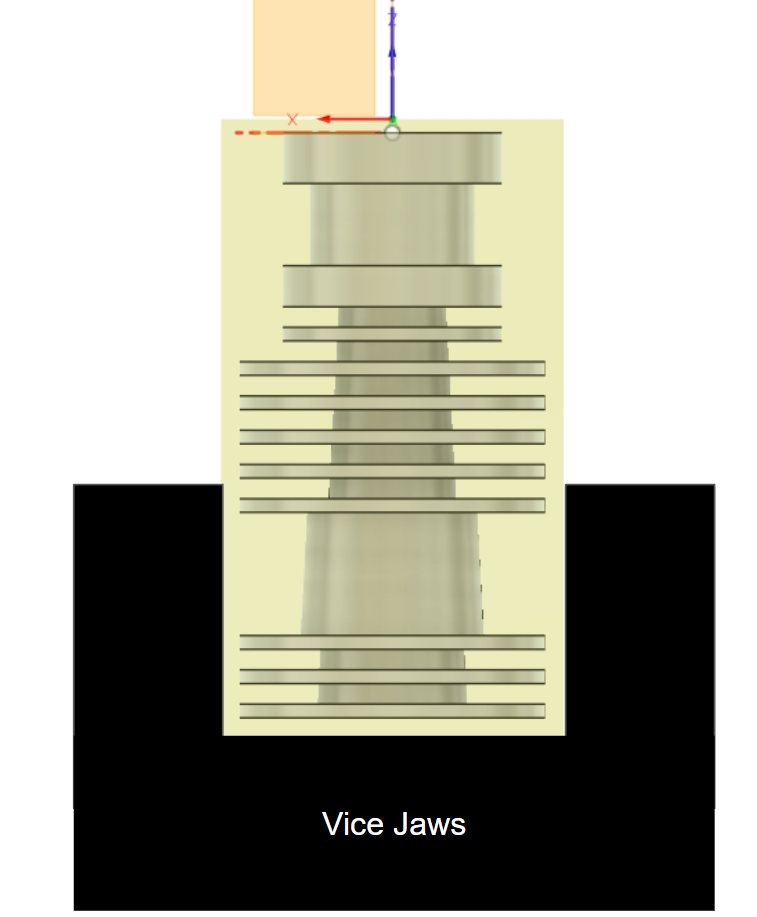
The design was detailed to production level: toleranced drawings (M4×0.7 nozzle thread, section views through the fin stack) and a two-setup CNC machining route planned around standard vice fixturing. The recommended operating window is ~20–25 mm³/s, pending physical validation by IR thermography and a flow–power benchmark.设计细化到可投产深度:带公差的工程图(M4×0.7 喷嘴螺纹、鳍片组剖视)以及围绕标准台钳装夹规划的两次装夹 CNC 工艺路线。推荐工作窗口 ~20–25 mm³/s,待 IR 热成像与流量–功率基准做物理验证。
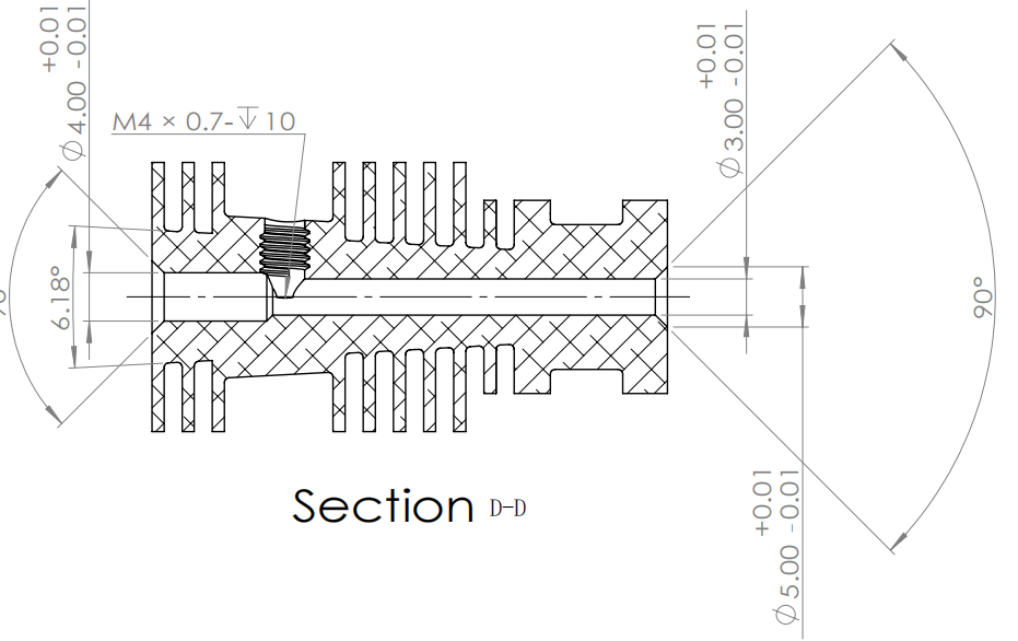
Toleranced section drawing of the heat-sink — Section D-D with the M4×0.7 tapped nozzle thread.
Toleranced Section D-D through the heat-sink, with the M4×0.7 tapped nozzle thread.散热器 D-D 剖视工程图,含 M4×0.7 喷嘴螺纹。
CNC workholding plan — the blank held in vice jaws for machining.
Workholding for the CNC route — the blank held in vice jaws, one of the two planned setups.CNC 工艺装夹——毛坯夹持在台钳中,两次装夹之一。
~0.96 M
quadratic elements in the thermal FEA热 FEA 二次单元数
4 → 1
pod concepts consolidated into the final designpod 概念整合为一个最终设计
20–25 mm³/s
recommended volumetric-flow window推荐体积流量窗口
BIW Welding-Line SCADA
NEXT PROJECT下一个项目

BIW Welding-Line SCADA车身焊装线 SCADA

A conceptual SCADA design for an automotive Body-In-White welding line, plus a physical evaluation of a low-cost K-type thermocouple chain f为汽车车身焊装(BIW)线做的概念级 SCADA 设计,加上对一条低成本 K 型热电偶链的物理评估,用于监测点焊电极冷却水温差 ΔT。MEC

Team · MEC5882